Hydraulic Seals and Pneumatic Seals » Hydraulic & Pneumatic Applications, Lip Loaded Seals
At Shalimar, we pride ourselves in our ability to design and manufacture the most durable hydraulic and pneumatic seals. Offering advanced materials and designed technology Shalimar has the ability to manufacture a wide array of seal options with differing fluid and temperature thresholds, surface speeds and pressures. Shalimar's Loaded lip U-Cups are used in a wide range of applications, some examples are listed below:
- Hydraulic Valves and Pneumatic Equipment
- Oil Drilling
- Pumps and Presses
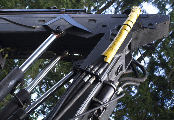
- Construction Equipment
- Industrial Machinery Mining Equipment
- Farm Machinery
- Off Road Equipment
 Hydraulic seals are designed specifically for sealing fluids of dynamic, linear and reciprocating motions.
Shalimar's Hydraulic & Pneumatic Applications Loaded Lip U-Cups
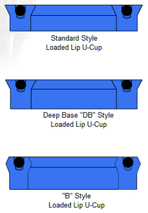
The Loaded Lip U-Cup is a very versatile seal because it can be used as a rod seal or piston seal. The energizer ensures constant pressure on the sealing lips. it is considered a multipurpose seal and is designed for significantly improved performanceShalimar offers three styles of the Loaded lip U-Cup: Standard, Deep Base, and "B" Styl. In addition, Shalimar will supply Loaded Lip U-Cups in various types of elastomers to meet your specific requirements. Please refer to the figure on the right column of this page which shows these various styles.
The Standard deign is usually symmetrical in cross section in which the height of the U-Cups is the same as the cross section.
The Deep Base (DB) U-Cup is the same basic design as the standard style except the height is taller
The "B" Style has a back beveled lip and generally the same height as the deep base, but functions with more lip interference. This design helps to ensure optimum sealing function. This style is particularly useful in high pressure conditions. In addition, the design of the "B" style loaded Lip U-Cup combines ease of installation with rugged construction for highly effective seal in heavy duty applications.
This series of sealants can be designed into the original equipment for significantly longer life than some of the other types of seals.
Operating Environments
Temperature is of primary importance since the pressure medium is always in contact with the packing. At high temperatures, the pressure medium may sometimes vaporize, thus causing it to be particularly penetrating. Packing must be specially treated to resist such conditions. It is imperative that maximum operating temperatures be considered when packing are selected.The chemical composition of all pressure mediums is of primary importance. Mediums used by many manufactures are by-products of the processes for which the hydraulic or pneumatic machinery is employed. Often, the result is that the chemically active liquids are the pressure media against which packing have to act. Use of a by-product is sound enough practice, provided that the chemical composition of the pressure medium is considered when packing are selected.
Depending on the specific application, Loaded Lip U-Cups are usually made of either Carboxylated Nitrite, Urethane, EPDM or Fluoroelastomer compounds. Again, the difference in material depends upon various application factors and operating environments.
Installation
It is important to remember that when installing Loaded U-Cups through or over threaded or other sharp projections to provide adequate clearance between the diameter of packing and projection (approximately 10% free cross section of the seal). The cylinder bore or rod should have a 25º maximum chamfer at its entrance to facilitate installation and to eliminate the possibility of damage to the seal. It is best for the seal to be entered on the chamfer, in its free state, before being forced into position.Finally loaded Lip U-Cups should be lubricated with suitable lubricant.
Design & Function
The pressure range for this packing is from vacuum to 5,000 psi, based on machine parts being within J.I.C. Standard tolerance and the type of elastomer from which the seal is made. Also the temperature range is dependent upon the type of elastomer from which the seal is made.
The energizer keeps the lips of the seal pressed against the sealing surfaces thus allowing the Loaded Lip U-Cup to seal under low pressure.
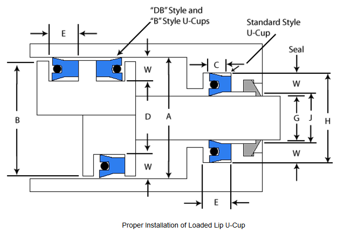
You will notice from the chart below that the groove axial length is a few thousandths of an inch more than the height of the Loaded Lip U-Cup. This allows the seal to float and helps it seal under slight side loads.
loaded Lip U-Cups give longer wear life because of a larger lip contact area than the live contact area of other conventional packing.
The energizer keeps the lips of the seal pressed against the sealing surfaces thus allowing the Loaded Lip U-Cup to seal under low pressure.
You will notice from the chart below that the groove axial length is a few thousandths of an inch more than the height of the Loaded Lip U-Cup. This allows the seal to float and helps it seal under slight side loads.
loaded Lip U-Cups give longer wear life because of a larger lip contact area than the live contact area of other conventional packing.
Although the loaded Lip U-Cups have exceptional resistance to abrasion, no seal should be expected to give long service when operating on poorly finished or pitted surfaces, scored cylinders or rods. The finish on both the rod and cylinder should be 10 rms to 16 rms. This finish not only smooth enough to keep the packing from tearing, it allows seepage and thus lubricates the seal.
Additionally there are other considerations when designing Loaded Lip U-Cups. Following are some cases.
In the back-to-back piston application as in a double acting piston, there is a need for the energizer to be removed to prevent pressure forming in between the seals. For these situations, it is recommended that the "B" style Loaded Lip U-Cup be used.
Specifications for Loaded Lip U-Cups, Including O.D., Height, Length and Diameters |
||||||||||
| Nominal Bore O.D & Range |
Nominal Radial Cross Section |
Piston O.D. |
Nominal Height Standard Style |
Nominal Height DB & B Style |
Seal I.D & Piston Groove Equation | Axial Seal Standard Style |
Groove Length DB & B Style |
Nominal Rod Diameter & Seal I.D. |
Housing Opening Diameter | Housing Grove Diameter |
| A | W | B | C | C | D | E | E | G | J | H |
| 5/16" To 6" Bore Tol. +.002 -.000 |
1/8" | A min -.001" Tolerance +.000 -.001 |
1/8" | 1/4" | A min -2(W) Tolerance +.000 -.002 |
.138" | .275" | 1/16" to 5 3/4" Rod Tol |
G max +.001" Tolerance +.002 -.000 |
G max +2(W) Tolerance +.002 -.000 |
| 1 1/16" to 1 3/4" Bore Tol. +.002 -.000 |
5/32" | A min -.001" Tolerance +.000 -.001 |
5/32" | 1/4" | A min -2(W) Tolerance +.000 -.002 |
.172" | .278" | 3/4" to 1 7/16" Rod Tol +.000 -.002 |
G max +.001" Tolerance +.002 -.000 |
G max +2(W) Tolerance +.002 -.000 |
| 9/16" to 6 11/16" Bore Tol. +.002 -.000 |
3/16" | A min -.001" Tolerance +.000 -.001 |
3/16" | 5/16" & 3/8" | A min -2(W) Tolerance +.000 -.002 |
.207" | .344" .413" |
3/16" to 6 5/16" Rod Tol +.000 -.002 |
G max +.001" Tolerance +.002 -.000 |
G max +2(W) Tolerance +.002 -.000 |
| 15/16" to 10" Bore Tol. +.003 -.000 |
1/4" | A min -.001" Tolerance +.000 -.002 |
1/4" | 3/8" & 9/16" | A min -2(W) Tolerance +.000 -.003 |
.275" | .413" .618" |
7/16" to 9/12" Rod Tol +.000 -.002 |
G max +.001" Tolerance +.003 -.000 |
G max +2(W) Tolerance +.003 -.000 |
| 1" to 7 5/8" Bore Tol. +.003 -.000 |
5/16" | A min -.002" Tolerance +.000 -.002 |
5/16" | 3/8" & 1/2" 9/16" & 5/8" |
A min -2(W) Tolerance +.000 -.004 |
.343" | .413" .550" .619" .688" |
3/8" to 7" Rod Tol +.000 -.002 |
G max +.002" Tolerance +.003 -.000 |
G max +2(W) Tolerance +.004 -.000 |
| 1 1/2" to 18" Bore Tol. +.004 -.000 |
3/8" | A min -.002" Tolerance +.000 -.002 |
3/8" | 5/8" | A min -2(W) Tolerance +.000 -.005 |
.413" | .688" | 3/4" to 17 1/4" Rod Tol +.000 -.002 |
G max +.002" Tolerance +.004 -.000 |
G max +2(W) Tolerance +.005 -.000 |